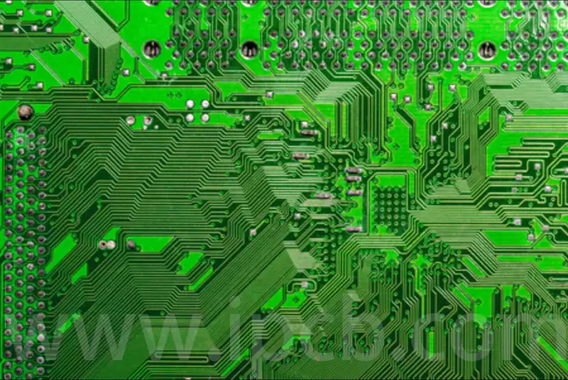
What is a pcb circuit board? A PCB circuit board, also known as a printed circuit board, is a board that forms electrical connections between electronic components by laying conductive copper foil patterns on the surface of insulating materials (such as glass fibre, epoxy resin, etc.). Its main function is to establish electrical connections between electronic components through these copper foil circuits and to support the components fixed on the board.
Whether it is simple household appliances, complex smart devices, or industrial control systems, none of them can function without the support of PCB circuit board.
Functions and Applications of PCB Circuit Board
PCB circuit board serves multiple functions in electronic devices. On one hand, they provide mechanical support for the mounting and assembly of various electronic components such as integrated circuits, enabling interconnections and electrical connections or insulation between components, and ensuring the required electrical characteristics. On the other hand, they also provide solder mask patterns for automated soldering, as well as identification characters and graphics for component insertion, inspection, and maintenance.
Furthermore, after adopting PCBs, the consistency of similar printed circuit boards eliminates errors caused by manual wiring, enabling automatic component insertion or mounting, automatic soldering, and automatic testing. This ensures the quality of electronic products, improves labour productivity, reduces costs, and facilitates maintenance.
Today, PCB circuit boards are widely used across various industries:
In the LED lighting sector, metal-core PCBs are widely adopted due to the minimal heat generated by LED bulbs during operation.
In the automotive industry, PCBs are used in engine control systems, audio systems, transmission sensors, digital displays, and more, ensuring the proper functioning of vehicles.
In the aerospace industry, PCBs must withstand extreme temperatures and turbulent conditions, requiring lightweight and corrosion-resistant components.
In the medical industry, PCBs support devices such as cardiac monitors, otolaryngology diagnostic equipment, and CT scanning systems.
In the military sector, PCB circuit boards must be highly durable and reliable under extreme conditions, undergoing rigorous testing to ensure design meets high-performance requirements.
PCB circuit boards are categorised into three main types based on the number of layers: single-sided PCBs, double-sided PCBs, and multi-layer PCBs.
Single-sided PCB circuit board: On the most basic PCB, components are concentrated on one side, while conductive traces are concentrated on the other side. Since conductive traces only appear on one side, this type of PCB circuit board is referred to as a single-sided PCB. Single-sided PCBs are typically simple to manufacture and cost-effective, but their drawback is that they cannot be used in overly complex products. Double-sided PCBs are an extension of single-sided PCBs. When single-layer routing cannot meet the requirements of electronic products, double-sided PCBs are used.
Both sides have copper-clad traces, and through-holes can be used to connect the circuits between the two layers, forming the required network connections. A multilayer board refers to a printed circuit board composed of three or more conductive pattern layers separated by insulating materials and laminated together, with the conductive patterns interconnected as required.
Multilayer printed circuit boards are the result of the development of electronic information technology towards high speed, multi-functionality, large capacity, small size, thinness, and light weight.
Single-sided PCB circuit board: On the most basic PCB, components are concentrated on one side, while conductive traces are concentrated on the other side. Since conductive traces only appear on one side, this type of PCB is referred to as a single-sided PCB. Single-sided PCBs are typically simple to manufacture and cost-effective, but their drawback is that they cannot be used in overly complex products. Double-sided PCBs are an extension of single-sided PCBs. When single-layer routing cannot meet the requirements of electronic products, double-sided PCBs are used.
Both sides have copper-clad traces, and through-holes can be used to connect the circuits between the two layers, forming the required network connections. A multilayer board refers to a printed circuit board composed of three or more conductive pattern layers separated by insulating materials and laminated together, with the conductive patterns interconnected as required.
Multilayer printed circuit boards are the result of the development of electronic information technology towards high speed, multi-functionality, large capacity, small size, thinness, and light weight.
Printed circuit boards can be classified by material properties into flexible boards (FPC), rigid boards (PCB), and flexible-rigid boards (FPCB).
Flexible boards are highly flexible, made of softer materials, and are used in electronic products that require expansion, bending, or three-dimensional assembly, such as cameras, camcorders, printers, and smartphones. The primary base materials include PI, LCP, and PPE;
Rigid boards, also known as rigid boards, were originally made from paper-based materials, but are now predominantly made from FR4. This involves weaving electronic-grade glass fibre into electronic fabric (similar to a loom principle), then impregnating it with resin and laminating copper foil on both sides. Their characteristics include high hardness, stability, and excellent insulation properties. Due to their high mechanical strength, these materials not only serve as conductive pathways for circuits but also act as a foundation for numerous micro-electronic components, earning them the title of ‘the mother of electronics.’
In the 5G era, to meet the demands of high-frequency and high-speed applications, new materials are continuously being developed. One notable example is PTFE, which offers greater flexibility compared to FR4 but also presents significant challenges in processing.
Classification based on material properties
Based on the flame-retardant properties of copper-clad laminates (CCL), they can be categorised into two types: flame-retardant (UL94-VO, UL94-V1) and non-flame-retardant (UL94-HB).
In recent years, with increasing emphasis on environmental protection, a new type of bromine-free CCL has emerged within the flame-retardant category, referred to as ‘green flame-retardant CCL.’ As electronic product technology continues to advance rapidly, higher performance requirements are being placed on CCL.
Therefore, based on performance classification, CCL can be further categorised into general-performance CCL, low-dielectric-constant CCL, high-heat-resistant CCL (with a general board temperature rating above 150°C), and low-thermal-expansion-coefficient CCL (typically used for packaging substrates), among other types.
Classification by PCB circuit board Surface Treatment
This classification is commonly used within factories and among technical personnel, primarily referring to standardised production processes. For example, classification by PCB surface treatment includes: leaded tin-plated boards (containing copper, tin, and lead), lead-free tin-plated boards (primarily composed of copper and tin, with trace amounts of nickel and silver/gold), gold-plated boards (containing copper, nickel, and gold), electroplated gold boards (containing copper, nickel, and gold), anti-oxidant or OSP boards (containing copper), gold finger boards (designed for plug-in applications with gold fingers on the board edges), electroplated silver boards, and selective electroplated gold boards, etc.
Types of special printed circuit boards
Metal core printed circuit boards Metal core printed circuit boards use a metal plate of equivalent thickness to replace epoxy glass cloth boards. After special processing, the conductive circuits on both sides of the metal plate are interconnected, while maintaining high insulation from the metal portion.
The advantages of metal core printed circuit boards include excellent heat dissipation and dimensional stability. This is because magnetic materials such as aluminium and iron have shielding properties, preventing mutual interference. Metal-core substrates, also known as heat-dissipating substrates, primarily utilise the heat-dissipating properties of metal. As electronic products become increasingly smaller, lighter, thinner, and shorter, and as the number of electronic components increases and integration levels rise, the rapid dissipation of heat generated by their functions has become a significant challenge. As a result, metal-core heat-dissipating substrates have emerged as a major category in applications involving high current and high-power products. Metal cores primarily include copper-based, iron-based, and aluminium-based types.
Carbon Film Printed Circuit Boards Carbon film printed circuit boards are printed circuit boards that form contacts or interconnections (with resistance values meeting specified requirements) by printing a layer of carbon film (conductive ink) on an insulating substrate. As the name suggests, carbon film refers to a thin layer formed by carbon ink particles adhered to an insulating substrate. Its main feature is the simple screen printing process, where conductive patterns are formed using conductive ink rather than the commonly used copper layer for traces. Additionally, conductive patterns can be added in one or two layers on single-sided printed circuit boards to achieve high-density routing. These conductive patterns not only serve as interconnections but also function as resistors, switch contacts, and electromagnetic shielding layers. Its process features include a simple production process, low cost, short lead time, excellent wear resistance, and conductivity, enabling single-sided boards to achieve high density, product miniaturisation, and lightweight design. It is suitable for keypad-type products such as televisions, telephones, game consoles, calculators, video recorders, and electronic pianos.
Liquid crystal displays in calculators, mobile phones, telephones, and many other electronic devices are essentially glass circuit boards! Both the liquid crystal and the circuits connecting it are fabricated on the glass surface, but they cannot be connected to external circuits via welding; instead, they must be mechanically connected using elastic soft contacts. A transparent glass-based circuit board where the glass substrate and conductive circuits are fused together, forming a tight bond. The surface of the glass substrate is flush with the upper surface of the conductive circuits, resulting in a smooth surface for the entire high-conductivity transparent glass-based circuit board. The conductive circuits are less prone to damage and have strong conductivity. The glass substrate is uniformly distributed with conductive holes that penetrate the glass substrate. These conductive holes contain hollow copper tubes with lengths equal to the thickness of the glass substrate, and the end faces of the hollow copper tubes are flush with the surface of the glass substrate. Both the upper and lower surfaces of the glass substrate are equipped with conductive circuits that are fused with the surface of the glass substrate, and the two conductive circuits are electrically connected through the hollow copper tubes. The conductive lines are made of graphene, or a conductive layer composed of a graphene layer on the surface and a metal layer fused with the glass substrate on the bottom, with the contact surfaces between the graphene layer and the metal layer being mutually fused. The glass substrate is a tempered glass plate.
Ceramic circuit boards are a type of ‘thermally conductive organic ceramic circuit board’ manufactured using thermally conductive ceramic powder and organic adhesives at temperatures below 250°C, achieving a thermal conductivity of 9–20 W/m·K. As electronic technology continues to penetrate various application fields, the high integration of circuit boards has become an inevitable trend. Highly integrated packaging modules require an excellent heat dissipation system, but the thermal conductivity (TC) limitations of traditional circuit boards such as FR-4 and CEM-3 have become a bottleneck constraining the development of electronic technology. The rapidly growing LED industry has also imposed higher requirements on the TC performance of the circuit boards it uses. In the field of high-power LED lighting, materials with excellent thermal conductivity, such as metal and ceramic, are often used to prepare circuit board substrates. The thermal conductivity of high-thermal-conductivity aluminium substrates typically ranges from 1 to 4 W/m·K, while the thermal conductivity of ceramic substrates can reach approximately 220 W/m·K, depending on their preparation methods and material formulations.
PCB circuit board primarily consists of copper-clad laminates (CCL), prepreg sheets (PP sheets), copper foil, solder mask (also known as solder resist), surface treatment, and characters.
1) Copper-clad laminates
Copper-clad laminates (CCL), also known as copper-clad boards or copper boards, are the basic materials for manufacturing printed circuit boards. They are composite materials consisting of a dielectric layer (resin, glass fibre) and high-purity conductors (copper foil). Copper-clad boards primarily provide three functions in printed circuit boards: conductivity, insulation, and structural support. The performance, quality, and manufacturing cost of printed circuit boards are largely dependent on the copper-clad laminate.
2) Semi-cured sheets
Semi-cured sheets, also known as PP sheets, are one of the primary materials used in the production of multilayer boards. They are primarily composed of resin and reinforcing materials, with reinforcing materials categorised into several types, including glass fibre cloth (abbreviated as glass cloth), paper-based materials, and composite materials. The semi-cured sheets (adhesive sheets) used in the production of multilayer printed circuit boards predominantly employ glass cloth as the reinforcing material.
3) Copper foil
Copper foil is a thin, continuous layer of metal foil deposited on the substrate layer of the circuit board. It serves as the conductive layer of the PCB, easily bonded to the insulating layer, and etched to form the circuit pattern.
Common industrial-grade copper foil can be broadly categorised into two types: rolled annealed (RA) copper foil and electrolytic (ED) copper foil:
Rolled annealed copper foil has better ductility and other properties, making it the copper foil of choice for early flexible circuit board manufacturing processes.
Electrolytic copper foil, on the other hand, offers the advantage of lower manufacturing costs compared to rolled annealed copper foil.
4) Solder mask
The solder mask refers to the areas on the printed circuit board coated with solder mask ink.
Solder mask ink is typically green, though some use red, black, or blue, so it is commonly referred to as ‘green ink’ in the PCB industry. It serves as a permanent protective layer for the printed circuit board, providing moisture resistance, corrosion resistance, mould resistance, and protection against mechanical abrasion, while also preventing components from being soldered to the wrong locations.
5) Surface treatment
Since bare copper is easily oxidised when exposed to air and prone to contamination, a protective layer must be applied to its surface. Common PCB surface treatment processes include leaded tin plating, lead-free tin plating, organic coating, gold plating, silver plating, tin plating, and gold-plated fingers. With the continuous improvement of environmental regulations, leaded tin plating processes have gradually been phased out.
6) Characters
Characters refer to the text layer on the topmost layer of the PCB circuit board, which may be omitted and is generally used for annotations. Typically, to facilitate circuit installation and maintenance, necessary markings, patterns, and text codes are printed on the upper and lower surfaces of the printed circuit board, such as component part numbers and nominal values, component outline shapes and manufacturer logos, production dates, etc. Characters are typically printed using screen printing.